Winding connection method of transformer winding deformation tester
Release Time : 2019-01-03 View Count : 次Transformer winding deformation tester is used to test 6kV and above power transformers and other special purpose transformers. In the process of operation or transportation, power transformers will inevitably suffer from the impact or physical impact of various fault short-circuit current. Under the strong electric force generated by short-circuit current, the transformer winding may lose stability and cause local distortion, this will seriously affect the safe operation of the transformer.
According to the national power industry standard DL / T911-2016, the frequency response analysis method is used to measure the winding deformation of transformer. The amplitude frequency response characteristics of each winding of the transformer are detected, and the detection results are compared vertically or horizontally, judges the possible deformation of transformer winding according to the change degree of amplitude frequency response characteristics.

The sweep signal of winding deformation frequency response test is suggested to be injected from the end of winding and output from the head end, and the non tested winding is suspended. According to the different wiring groups of transformer, the wiring mode of winding deformation test is also different.
YN wiring
The input impedance of sweep signal is connected to neutral point 0, and the output impedance of sweep signal is connected to A, B and C respectively. This measurement method can absorb the interference signal received on the non measurement phase by the low impedance of the signal generator. As shown in Figure 2.

Fig. 2 YN wiring
Y connection
Since the neutral point is not led out, the wiring shall be connected as follows, as shown in Fig. 3.
The input impedance is connected to A and the output impedance is connected to B for test.
The input impedance is connected to B and the output impedance is connected to the C for test.
The input impedance is connected to C and the output impedance is connected to A for test.

Fig. 3 Y wiring
Internal connection △ Wiring
The wiring mode of internal connection Δ connection winding is shown in Fig. 4. The input impedance is connected to c and the output impedance is connected to phase a, representing phase a.
The input impedance is connected to a, and the output impedance is connected to phase b, representing phase b.
The input impedance is connected to b and the output impedance is connected to phase c, representing phase c

Fig. 4 internal connection Δ connection
Because the two non measuring windings of internal connection Δ wiring are connected in series and connected in parallel in the circuit, it has an impact on the test process theoretically. If the attenuation is more than 10dB, it can be considered that the effect of non measurement coil can be ignored.
External connection Δ wiring
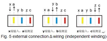
If the winding is uncoupled, the connection mode of measurement is shown in Fig. 5. If the connection is not untied, it can be regarded as internal connection Δ connection, and the wiring mode is shown in Fig. 3.
The input impedance is connected to x and the output impedance is connected to phase a, representing phase a.
The input impedance is connected to y and the output impedance is connected to phase b, representing phase b.
The input impedance is connected to Z and the output impedance is connected to phase c, representing phase c.

Transformer with balance winding
For the transformer with balance winding, the grounding must be disconnected during the test. As shown in Figure 6.

Figure 6 balance winding connection


